


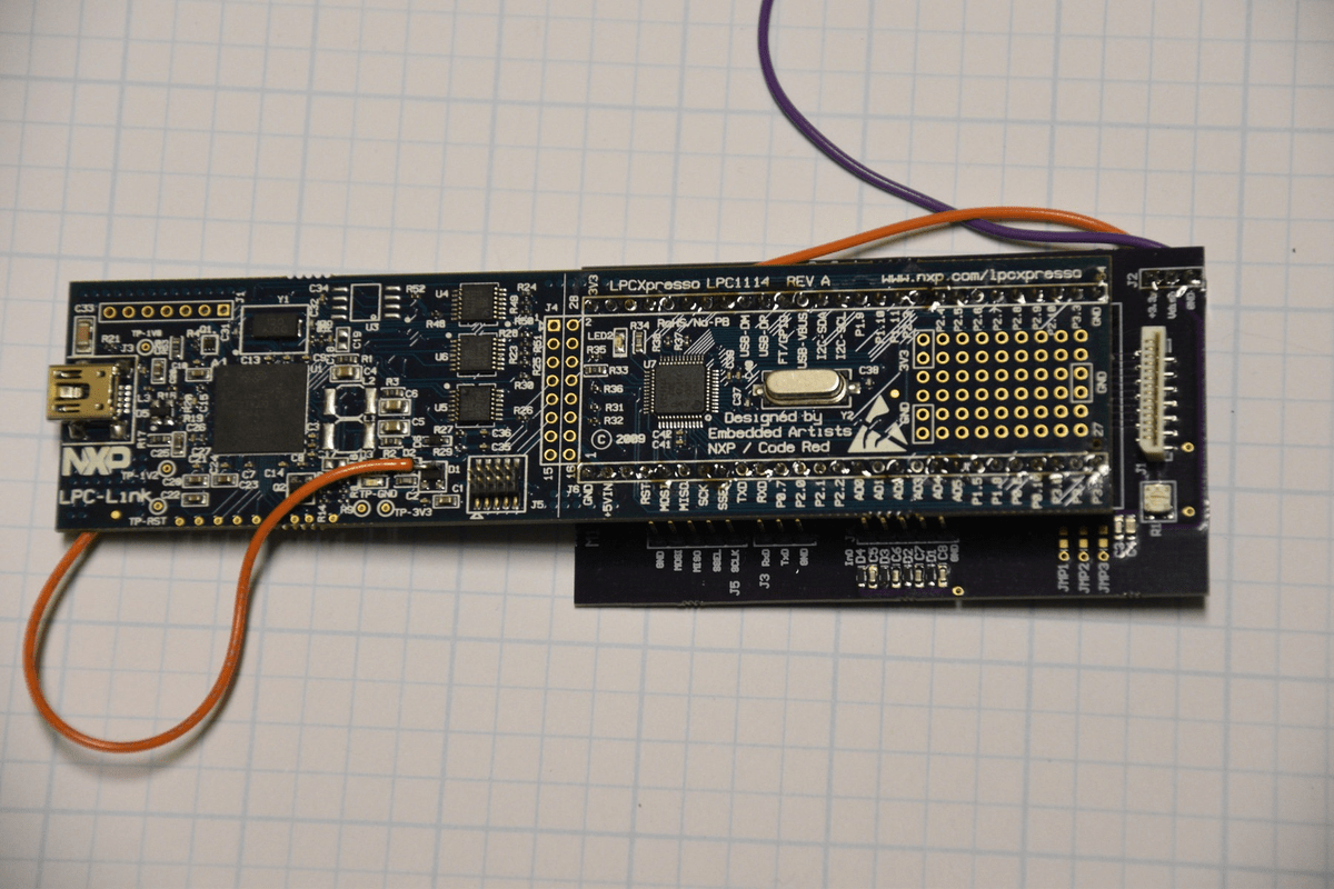
what the FTDI sends must be received by the target, and vice versa. Connect these to the target as needed (those boards all differ), but make sure to cross the RX and TX lines, i.e. It uses 4 pins, from top to bottom on the FTDI board: RX, TX, +5V, GND. Here is an example using an FTDI interface, as commonly used with ATmega’s / Arduinos: It explains the steps needed, every time a PDP-8 computer is turned on! That’s right: toggling switches to enter the boot loader… Serial upload If you think this is tedious: watch this 3-min video. Since this boot loader in stored in flash memory, it will then run whenever the ♜ is reset.
Once done, it will be running the secondary boot loader we just installed on it.
The purpose of this exercise is to prepare our board for use – not to go through these steps every time.
Our blank chip is too dumb for anything else. As should be clear by now, there’s no other way with STM32F103 chips than to either use STM’s serial ROM boot, or SWD. Let’s upload some code onto a new STM32 ♜ board (or one with unknown / incorrect code on it).